Subtotal: ₨ 1,000
When to CNC Machine Your 3D Printed Parts Leave a comment
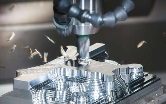
Computerized numerical control (CNC) machining has been around because of the early Nineteen Fifties and is one of the maximum famous low quantity production processes. Starting with a big block of uncooked fabric, a device turbines away fabric alongside a pc specific route to create an element. These programmed device paths can reduce extraordinarily particular and repeatable geometries in a whole lot of plastic and metallic materials.
CNC machining is historically used to fabricate low quantity, end-use components, however, it has additionally been followed as a secondary technique for additive production technology. Companies regularly will 3-D print plastic or metallic components after which CNC gadget them for the subsequent reasons:
– Dimensional accuracy – Industries with excessive practical and tolerance requirements, together with automotive, clinical, and purchaser merchandise production, want to hit repeatable, tight specs. Most additive production technology, together with Fused Deposition Modeling (FDM) and Direct Metal Laser Sintering (DMLS) can acquire up to ±0.1/2 in., however, that’s now no longer sufficient for a few essential element functions. With CNC machining you could deliver tolerance down to ±0.002 in. that could make a big distinction if you’re generating a meeting aid, production fixture, or any in-technique device with an extended carrier life.
– Speed – The 2d motive why agencies integrate the 2 technology is speed. Accounting for print time, CAD/CAM installation, and machining, the technique remains a great deal quicker than designing and generating a device for injection molding. And 3-D printing and machining deliver engineers greater flexibility withinside the timeline to make layout improvements. It simply includes updating CAD/CAM files, and printing and machining a brand new element, while making adjustments to an injection molding device may be almost not possible and expensive, inflicting predominant delays in manufacturing.
The maximum broadly used machining method for additive synthetic plastic components is horizontal or vertical 3-axis milling due to its capacity to transport withinside the X, Y, and Z planes. For greater complicated functions and geometries, we endorse 5-axis milling, that could rotate and tilt at the A and B-axis to attain undercuts and small functions.
Parts crafted from direct metallic laser sintering (DMLS) are regularly designed for annoying programs so they’re nearly usually machined with multi-axis milling to acquire particular floor dimensions. For excessive-cost manufacturing metallic components, agencies will practice a micro-machining technique that mixes a chemical response with a fluid float elimination technique to create a mirror-like floor quality. This polished floor end is regularly wanted for rubber gaskets to create a decent seal.
If your software calls for unique dimensions, you’ll want to modify your element’s 3-D CAD facts accordingly. There are some matters to do not forget whilst making ready your layout files:
– Build-in extra fabric – Additional fabric desires to be constructed into the uncooked 3-D published element so that after it’s machined, there are sufficient layers for the device to put off to acquire the proper spec.
– Note regions of tight tolerance – When consulting with the carrier bureau undertaking engineer make certain to reveal them the essential dimensions with a purpose to want to be machined. Often they endorse layout changes to optimize the construct for machining, together with growing positive wall thicknesses or going up a tip size.
– Make essential functions available – Place additives that want to be machined to spec in an easy-to-attain area. Even 5-axis turbines can’t attain a few 3-D published geometries so circulate software-essential functions to a device-available spot if possible.

 Boya Mic M1 Lavalier Collar Microphone for Canon Nikon DSLR Camcorder & Phone Android iPhone BY-M1 Mic in Pakistan